3d design
Although I am an electrical engineer first, CAD and manufacturing techniques such as laser-cutting, 3d printing, and metal machining have been useful editions to my toolkit.
From machining my own sterling engine out of aluminum and brass to 3d printing enclosures for PCBs, 3d design has allowed me to create more refined projects.
Rapid Prototyping
Although it was never required to take mechanical engineering classes, being able to use CAD and 3dprint / laser-cut has allowed me to make mounts and enclosures for my EE projects.
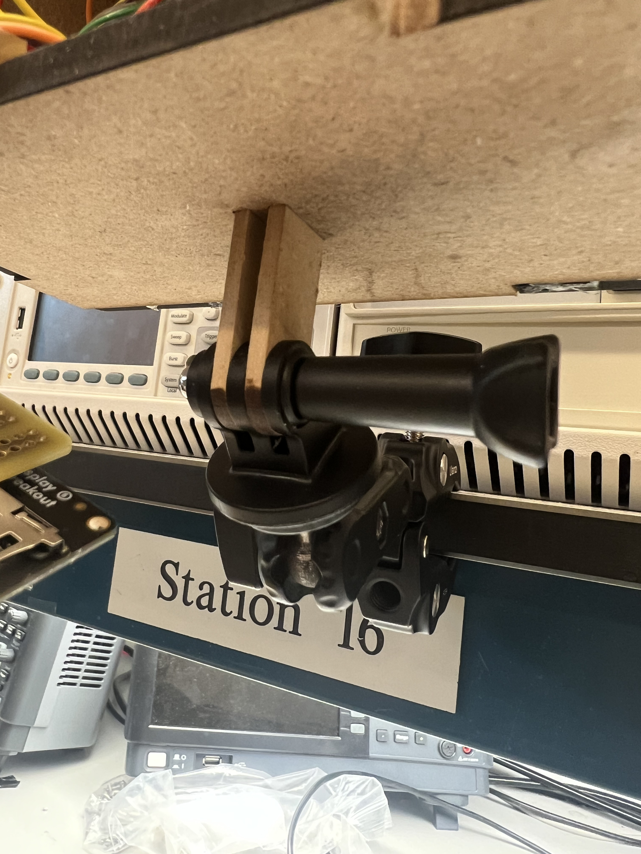
The top image is an enclosure I laser-cut from MDF that used a go-pro style mount. Building an enclosure that was GoPro compatible allowed me to easily .
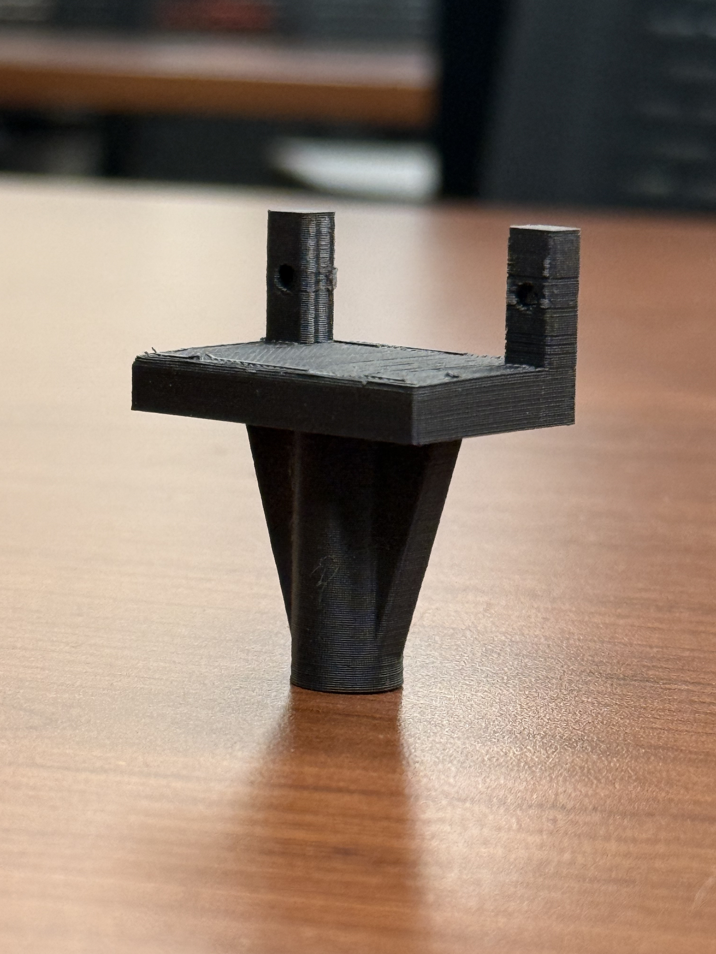
The second image is a mount for a servo I created. This allowed for the positioning of the solar panel in the EE project, SkyScan.
Stirling Engine
Inspiration
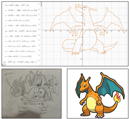
As a fan of Pokémon games, I have often defaulted to creating Charizard in my school projects.
Above is a 7th grade algebra project that I drew inspiration from, and below is an early sketch for my MEAM 2010 stirling engine design
Manufacturing
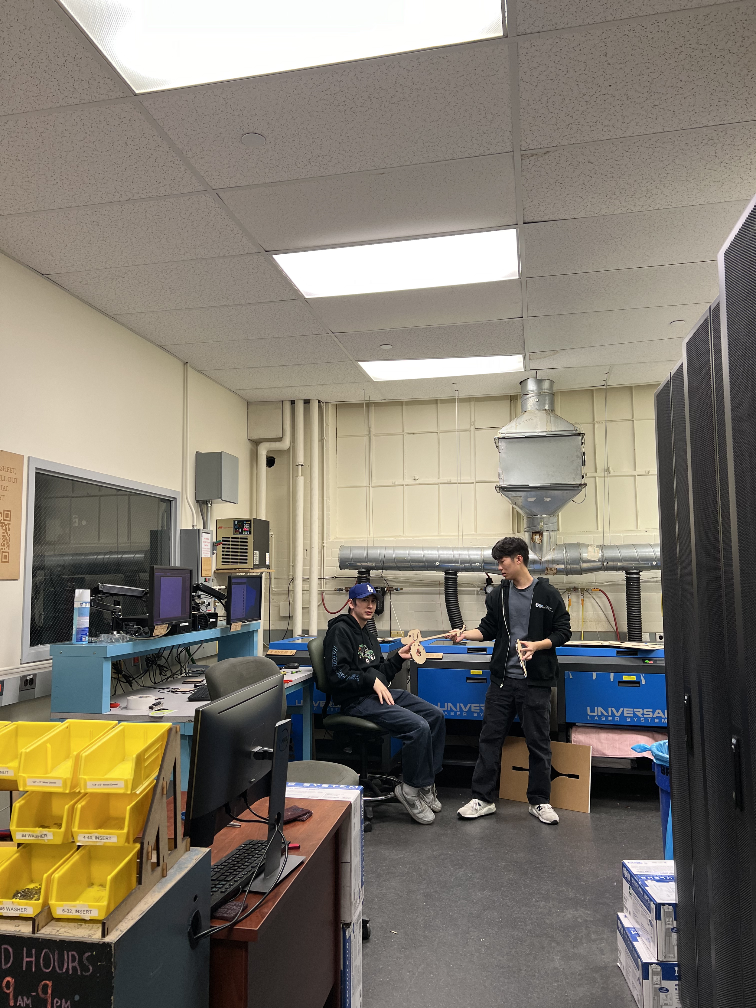
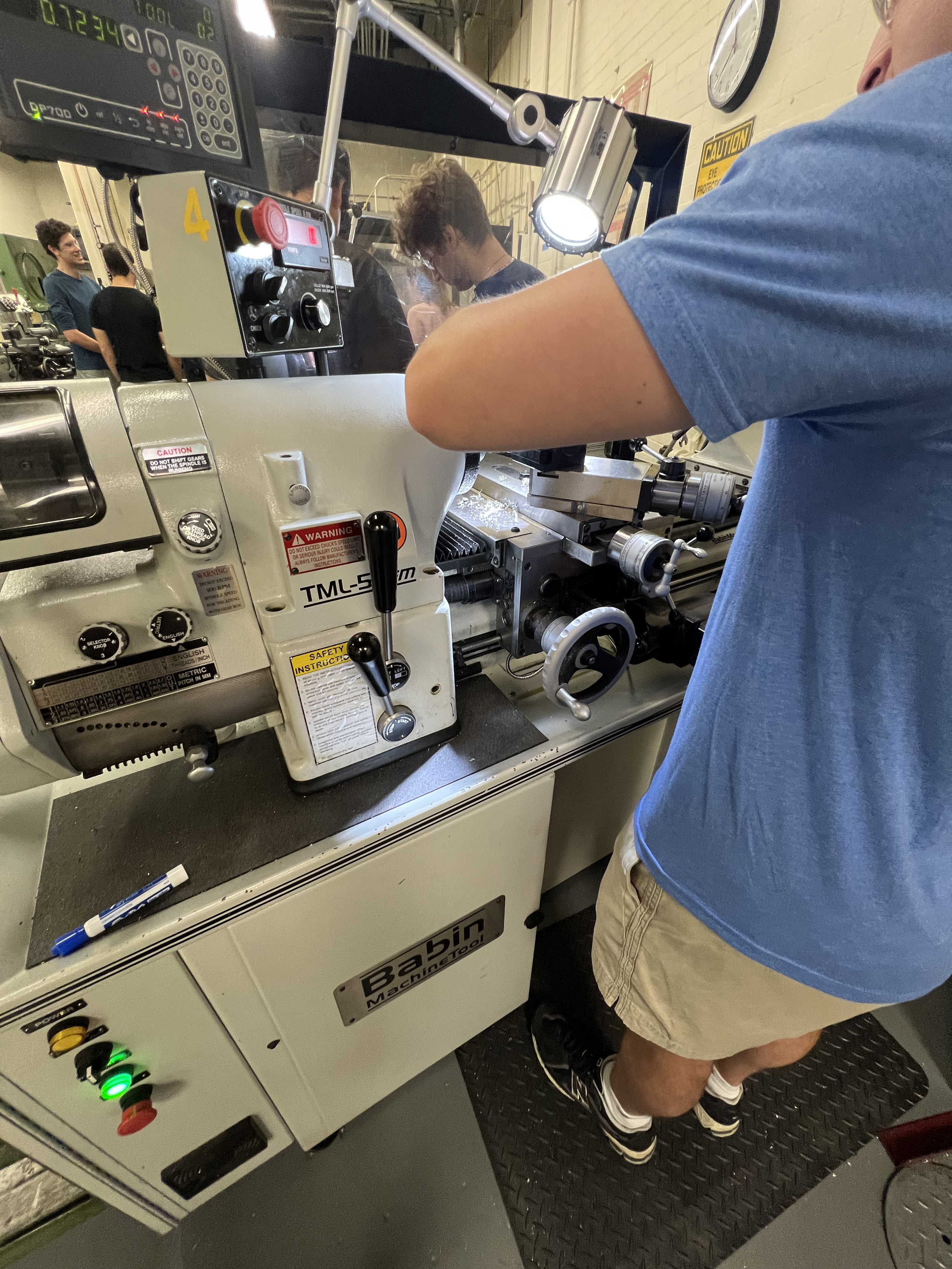
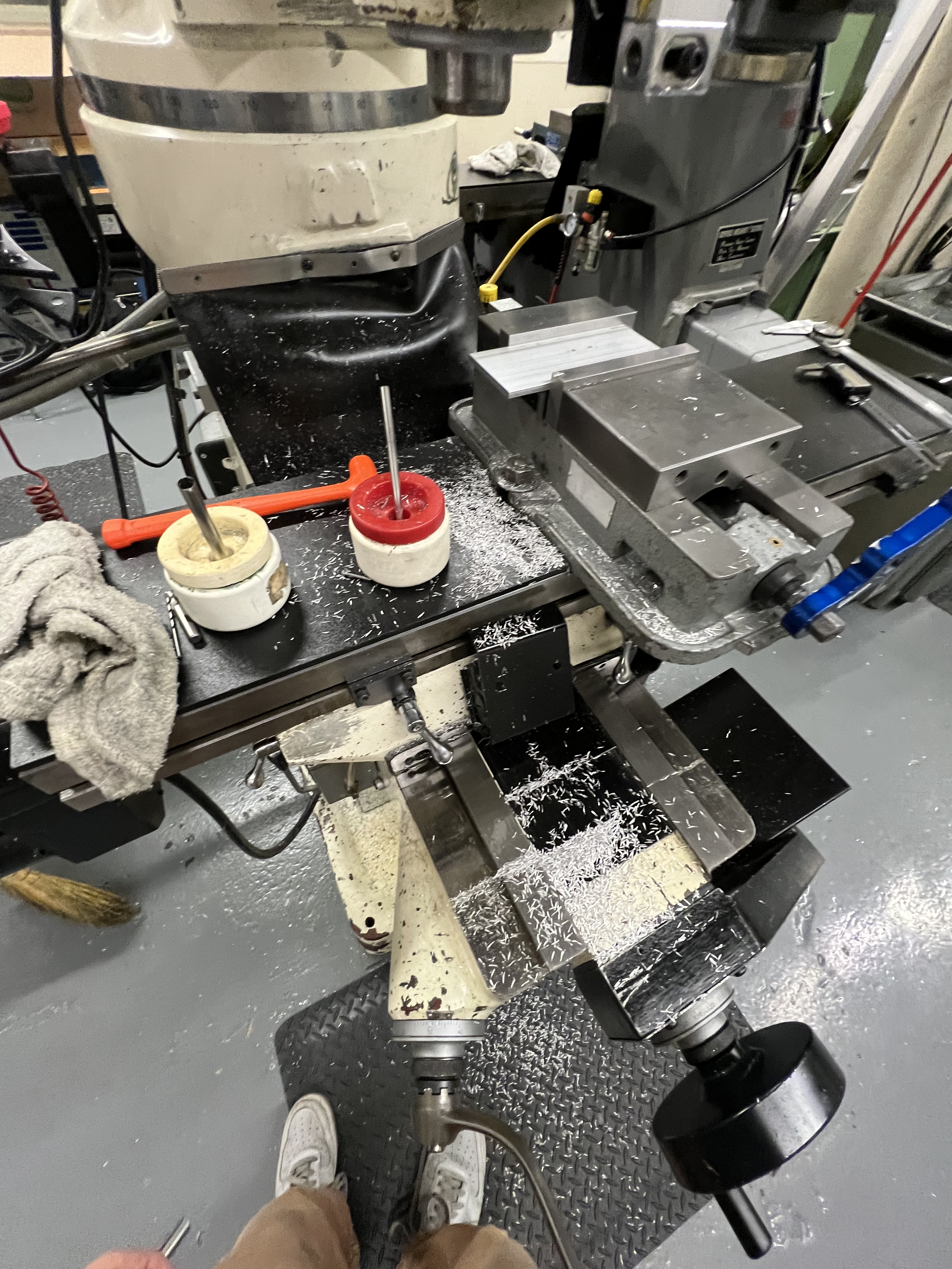
Designing the Stirling engine required meticulous precision. Over the course of the semester, I had spent many hours over many weeks in the Precision Machining Laboratory.
I worked with bandsaws, mills, and lathes to produce the many intricate pieces that went into the engine.
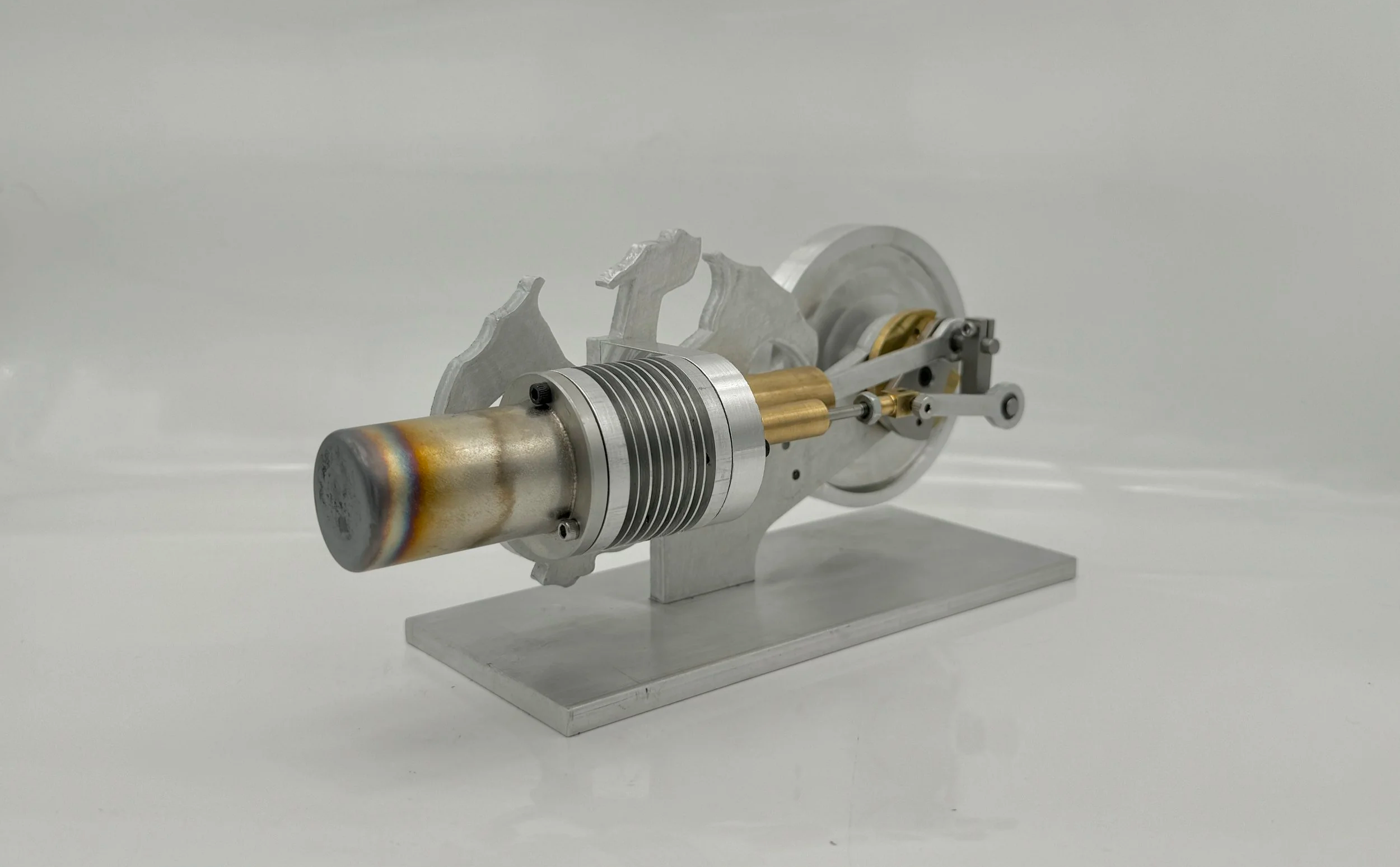
Results
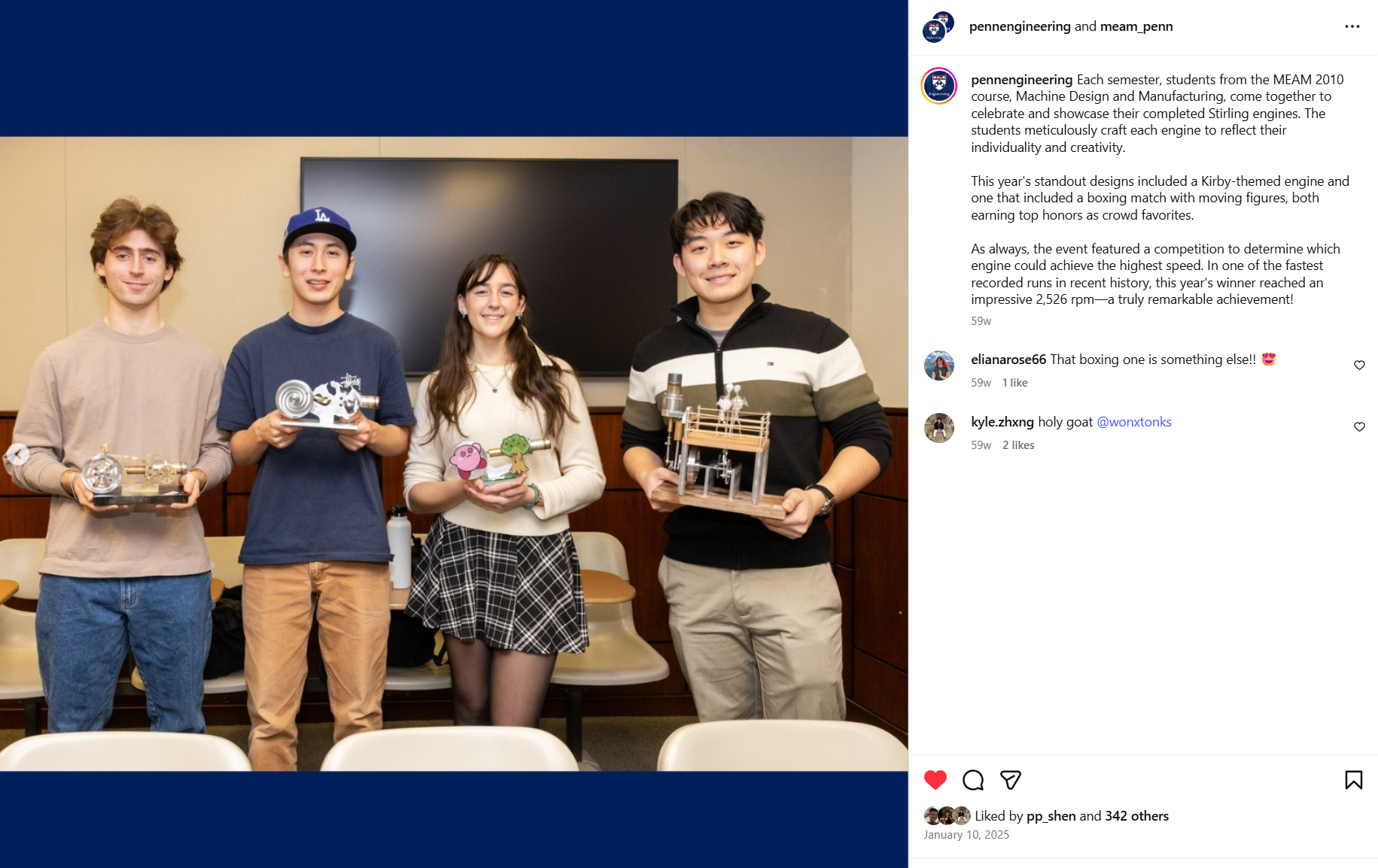
At the end of the semester, I had created a fully working stirling engine.
In fact, it was able to reach a speed of 2526 rpm which was the fastest engine of my class that semester. Thanks to my careful work, my engine and I made it on to the University of Pennsylvania Mechanical Engineering Instagram page!